"Failure is an option here. If things aren't failing, you aren't innovating enough."
-Elon Musk
"Failure is an option here. If things aren't failing, you aren't innovating enough."
-Elon Musk
During my 2B school term, one of my projects was making a CNN to distinguish between images of dogs and cats. I trained the CNN using the GPU on my laptop, which was powerful at the time, but getting old. Training took longer than I would have liked, resulting in a final model that did not perform as well as I had hoped. Between this experience and the fact that my laptop was starting to have trouble running the games I wanted to play, I decided I wanted to get a new computer.
At the time, I was using GRUB to dual boot Ubuntu and Windows. Over the course of the project I did in 2B, I ran into numerous problems with dual booting, including when Windows at one point appeared to remove Grub from the startup process. Tired of dealing with these problems, I decided I needed a better dual booting solution. I did a bit of research online, and this is what I came up with!
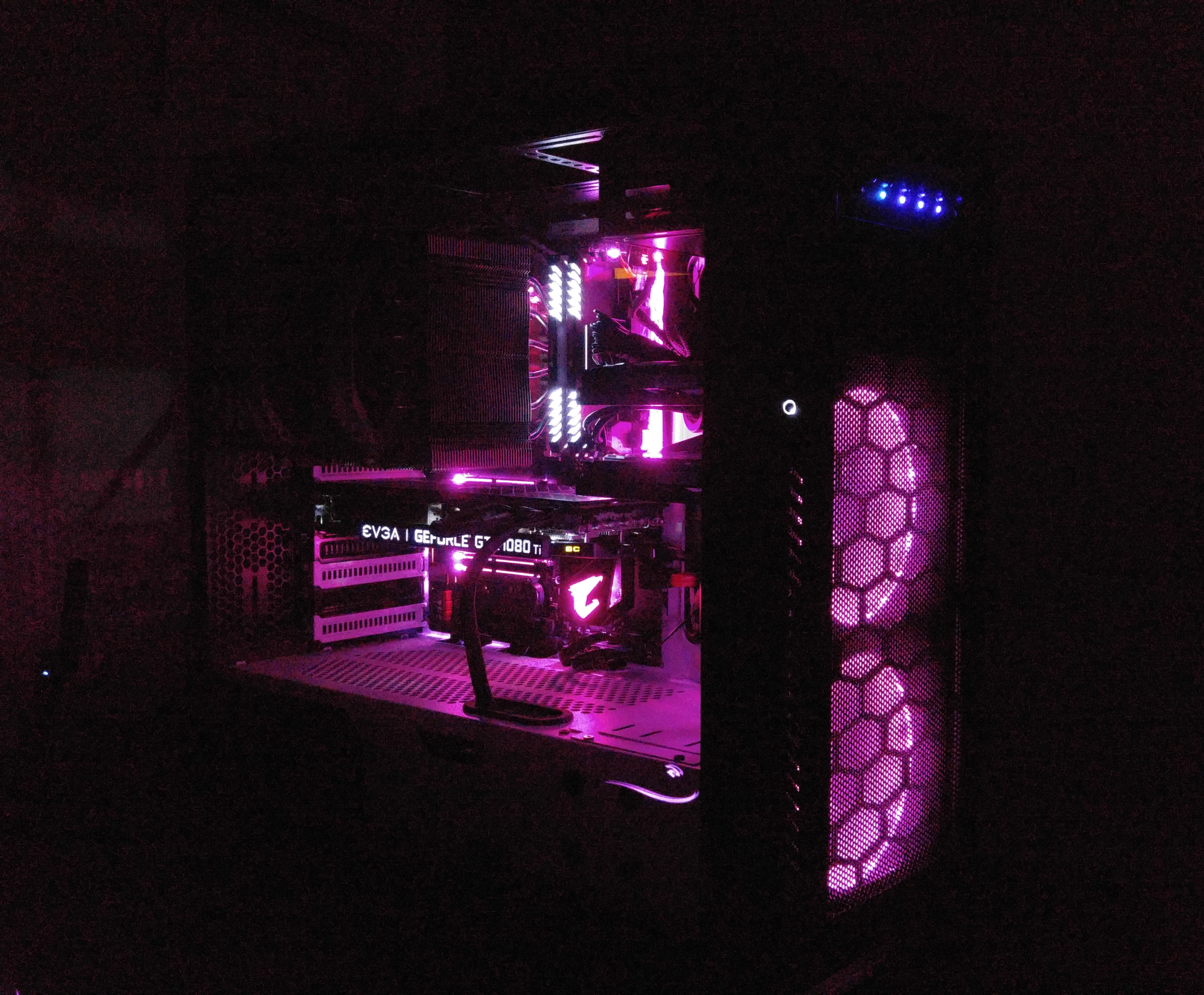
To avoid having to use a boot manager, I built my computer with a physical switch in the front, allowing me to disconnect/reconnect hard drives as needed every time I shut down. Currently, the system runs Ubuntu, and Windows. Each system is equipped with one SSD, and at least one hard drive.
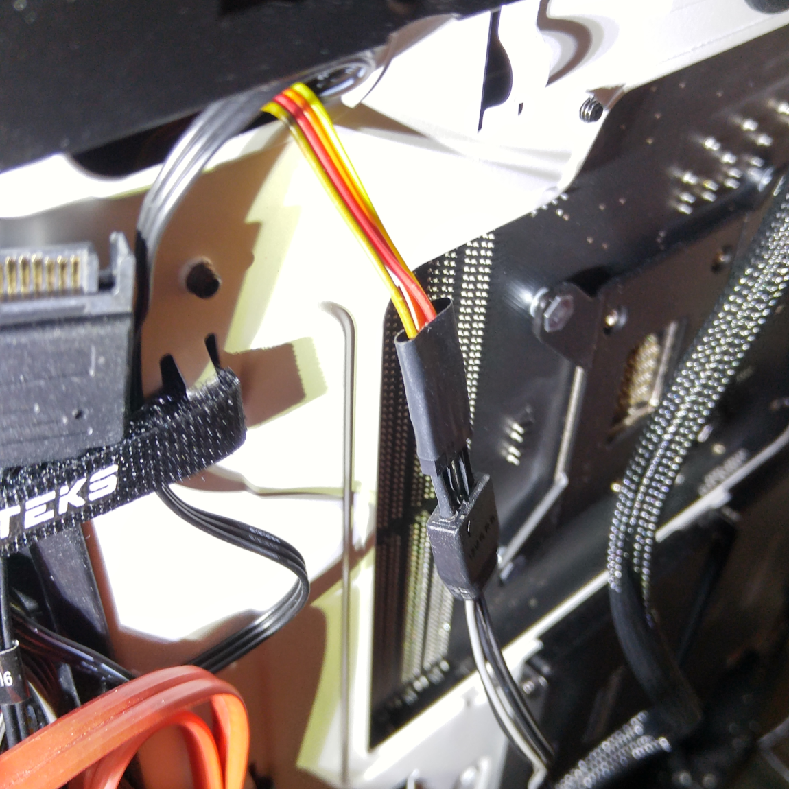
I built the computer over the Christmas Holidays and for the most part, it went smoothly. The only problem I ran into was at the very end, when I was trying to connect the RGB lights from the case to the ones on my motherboard. The Phanteks case I was using had a proprietary connector, that I would need to buy an adapter for if I wanted to connect it to the RGB headers on my motherboard. Unfortunately, when I looked for it on Amazon, it was expensive, out of stock, and would not arrive before the end of the holidays. To deal with the problem, I took some hobby wiring that I had left over from a previous hardware project and attached it to the RGB headers on the motherboard. I then attached those wires to the Phanteks connector using the ends of some resistors I had left over from another project. After covering everything with electrical tape, I booted the computer up and the case lights were working! Some pictures are below!
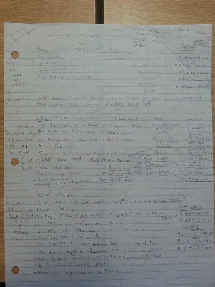
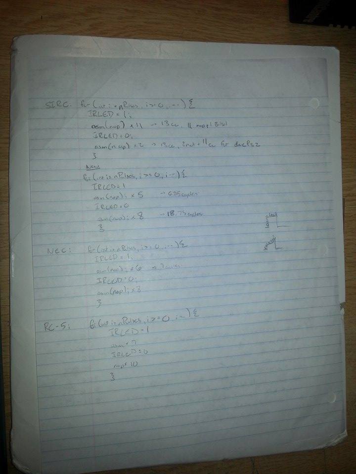
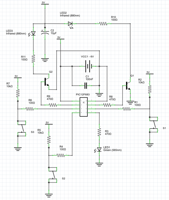
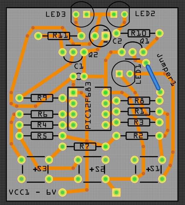
For my final project in my Grade 12 Computer Technology class, I decided to create a universal television remote. It was to use the SIRC, NEC, and RC5 Infra Red Protocols to transmit power and volume codes to multiple different types of televisions. I designed the circuit and the board in a program called Fritzing. I created the board layout by printing the design onto an overhead, and placing it on a blank board made of Fibreglass covered in copper and a photosensitive coating. The combination was exposed to UV light. This caused the photosensitive coating covering the copper to dissolve. I then placed the board in an etching solution, and etched away the exposed copper, leaving the circuit board. Because of the method used, I was only able to make the board single sided. I chose to drive the LEDs using transistors to allow more current to flow through the LEDs. The code for the remote can be found on my Github.
I also wrote up a technical report on this project. It can be downloaded here:
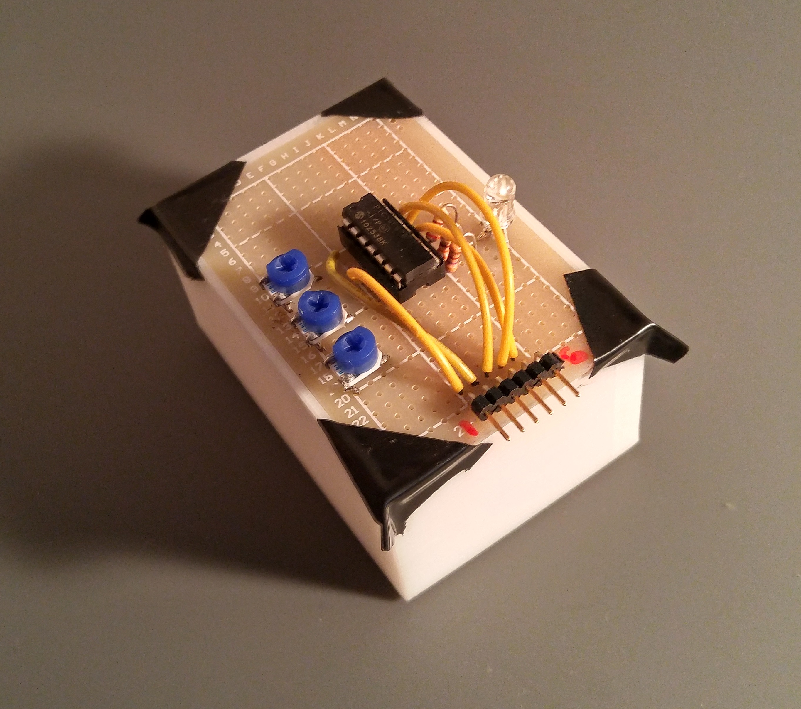
Because the circuit boards I made in both high school projects are one sided, I chose to simplify the design by not adding a programming connector to either of them. I instead created a separate board to connect my chip to a programmer, and test its analogue capabilities. The frame for the board was designed with Autodesk Inventor and 3D printed. The board includes 3 potentiometers, and an RGB LED. It is designed to be tested with the PIC16F676 microprocessor but can also program any 8 pin PIC chip as both chips share the exact same pin numbering on the top 8 pins. For the PIC16F676 I made an analogue test program. Running the code on the processor causes each of the colours on the RGB LED to vary in brightness based on the position of the potentiometers. The code can be found on my Github.
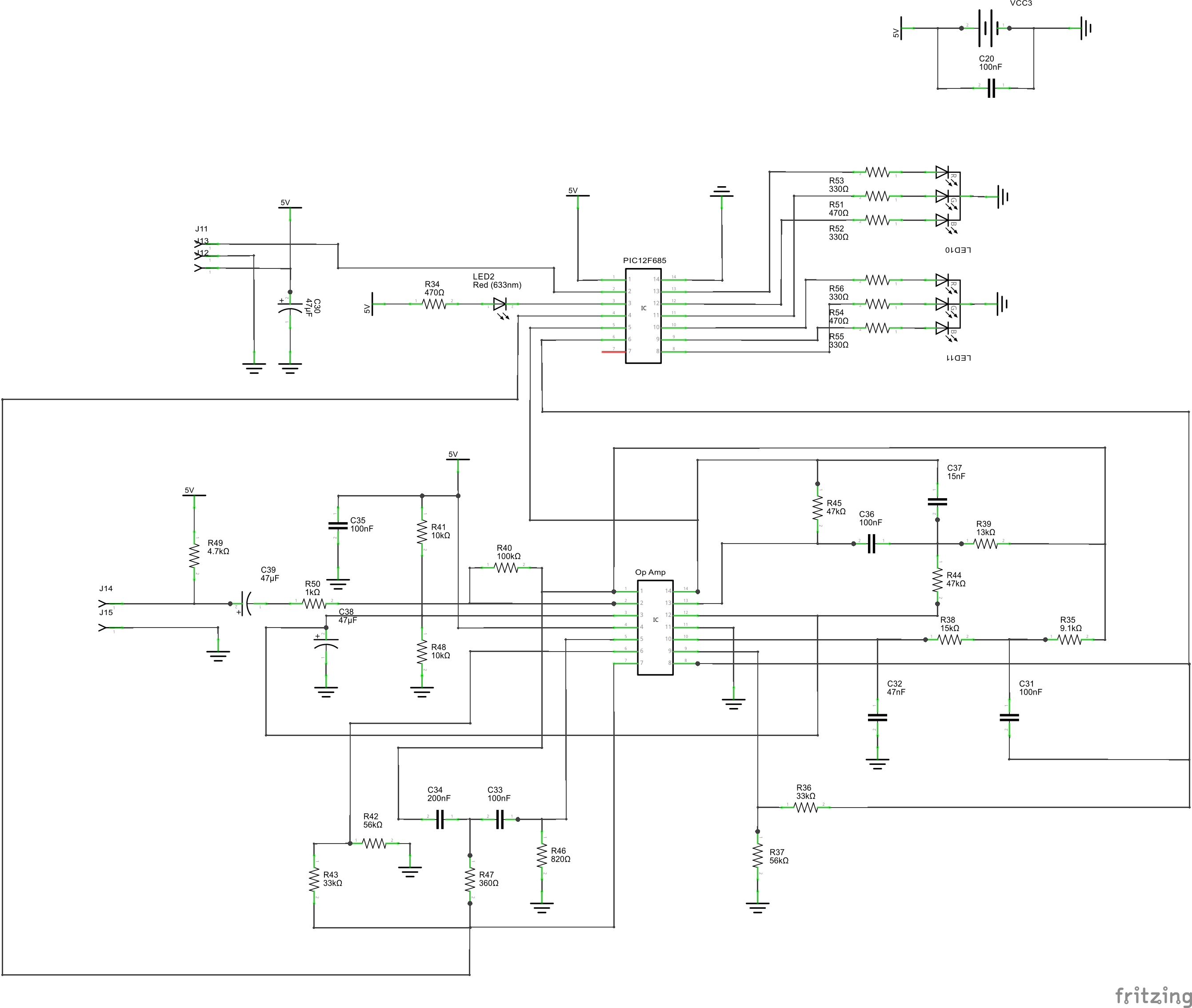
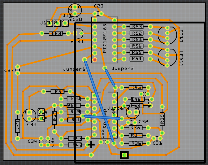
In Grade 12 Robotics Club, I designed a circuit board that would make lights flash based on musical frequencies. I used an op amp and 3 filter circuits to complete the project. My friend Gaurab Aryal helped solder the parts in. The same software and procedure used for the television remote was used here. With the help of my teacher Mr. Rampelt, I wrote an Analogue to Digital conversion program for the board using the Analogue Test board, and plan to test it when I get a chance to solder in the battery pack.